VRF lite CISCO podstawy
by admin · Październik 6, 2017
VRF (Virtual routing and forwarding) to technologia, która umożliwia podzielenie routera na logiczne routery, z których każdy posiada osobną tablicę routingu. Dzięki temu możliwe jest używanie tej samej adresacji na różnych interfejsach. Działa to podobnie jak vlany na switchach. W przypadku vlanów przypisujemy interfejs do odpowiedniego vlanu, natomiast w przypadku vrf przypisujemy interfejs do odpowiedniego vrf’a.
W poniższym przykładzie pokażę jak skonfigurować VRF na routerach CISCO.
PRZYKŁAD
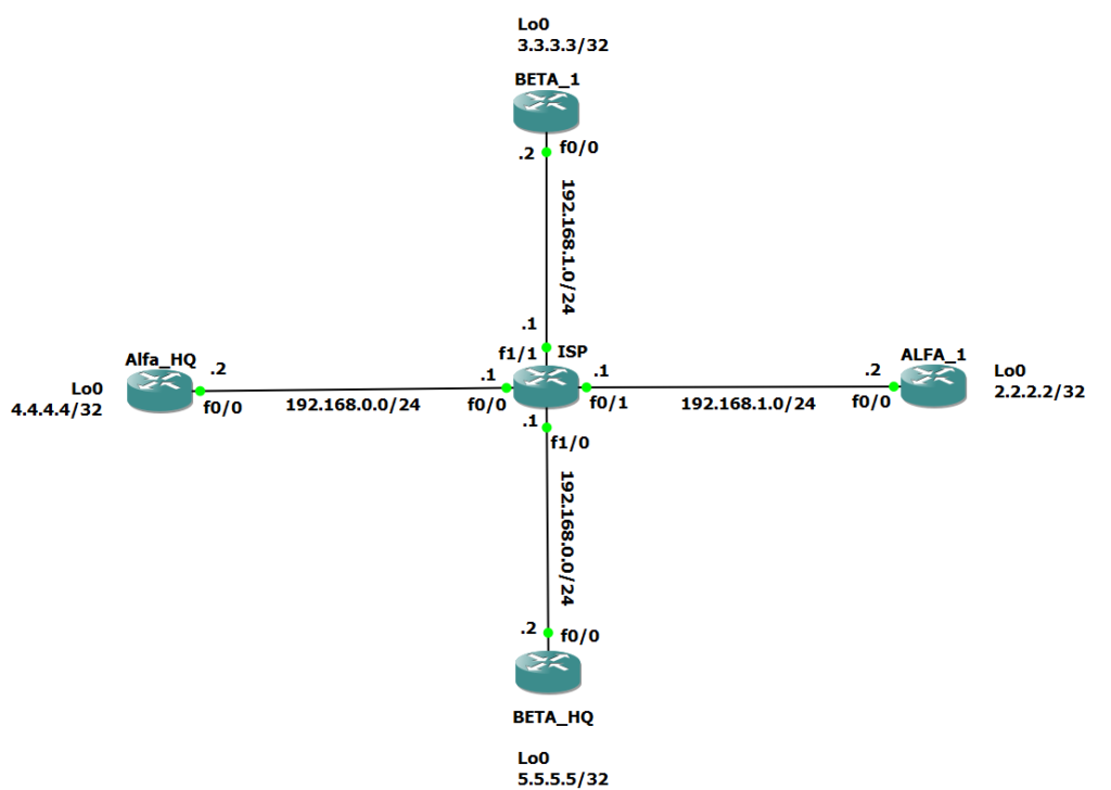
Załóżmy że mamy jesteśmy operatorem sieciowym (ISP), który świadczy usługi dla firmy ALFA i BETA. Obie firmy posiadają dwa oddziały (centralę HQ i oddział zdalny). ISP ma zapewnić łączność pomiędzy oddziałami dla obu firm i ma to zrobić w taki sposób żeby sieć firmy ALFA była odseparowana od sieci firmy BETA. Dodatkowo firma ALFA jak i firma BETA korzystają z tych samych adresacji. Operator może zakupić dwa routery i na jednym świadczyć usługi dla firmy ALFA a na drugim dla firmy BETA, jednak lepszym rozwiązaniem będzie zastosowanie VRF, które spełnią wymagania obu firm i nie wymagają dodatkowego sprzętu.
Topologia sieci wygląda następująco:
ALFA
Konfiguracja – ALFA_HQ
interface Loopback0
 ip address 4.4.4.4 255.255.255.255
!
interface FastEthernet0/0
 ip address 192.168.0.2 255.255.255.0
Konfiguracja – ALFA_1
interface Loopback0
 ip address 2.2.2.2 255.255.255.255
!
interface FastEthernet0/0
 ip address 192.168.1.2
BETA
Konfiguracja – BETA_HQ
interface Loopback0
 ip address 5.5.5.5 255.255.255.255
!
interface FastEthernet0/0
 ip address 192.168.0.2
Konfiguracja – BETA_1
interface Loopback0
 ip address 3.3.3.3 255.255.255.255
!
interface FastEthernet0/0
 ip address 192.168.1.2
ISP VRF
Konfigurację ISP zaczniemy od skonfigurowania interfejsów do których podłączone są oddziały Alfa_HQ (fa0/0) i Beta_HQ(fa1/0):
ISP(config)#int fastEthernet 0/0
ISP(config-if)#ip address 192.168.0.1 255.255.255.0
ISP(config-if)#no sh
ISP(config-if)#exit
ISP(config)#int fastEthernet 1/0
ISP(config-if)#ip address 192.168.0.1 255.255.255.0
% 192.168.0.0 overlaps with FastEthernet0/0
ISP(config)#ip vrf BETA
ISP(config-vrf)#exit
ISP(config)#ip vrf ALFA
Teraz musimy podpiąć interfejs pod VRF, służy do tego komenda: ip vrf forwarding NAZWA_VRFu (Uwaga: dodanie interfejsu do VRF skutkuje usunięciem adresu IP z intefejsu, należy o tym pamiętać przed konfiguracją VRFu na interfejsie):
ISP(config)#int fastEthernet 0/0
ISP(config-if)#ip vrf for
ISP(config-if)#ip vrf forwarding ALFA
% Interface FastEthernet0/0 IPv4 disabled and address(es) removed due to enabling VRF ALFA
ISP(config)#int fastEthernet 1/0
ISP(config-if)#ip vrf for
ISP(config-if)#ip vrf forwarding BETA
Spróbujmy teraz skonfigurować adresy IP na interfejsach fa0/0 i fa1/0:
ISP(config)#int fastEthernet 0/0
ISP(config-if)#ip ad
ISP(config-if)#ip address 192.168.0.1 255.255.255.0
ISP(config-if)#no sh
ISP(config-if)#exit
ISP(config)#int fa
ISP(config)#int fastEthernet 1/0
ISP(config-if)#ip add
ISP(config-if)#ip address 192.168.0.1 255.255.255.0
Jak widać dzięki zastosowaniu VRFów mogliśmy skonfigurować te same adresy IP na dwóch różnych intefejsach.
Pełna konfiguracja routera ISP wygląda następująco:
ISP(config)#int fastEthernet 0/0
ISP(config-if)#ip address 192.168.0.1 255.255.255.0
ISP(config-if)#ip vrf forwarding ALFA
ISP(config)#int fastEthernet 0/1
ISP(config-if)#ip address 192.168.1.1 255.255.255.0
ISP(config-if)#ip vrf forwarding ALFA
ISP(config)#int fastEthernet 0/0
ISP(config-if)#ip address 192.168.0.1 255.255.255.0
ISP(config-if)#ip vrf forwarding ALFA
ISP(config)#int fastEthernet 1/0
ISP(config-if)#ip address 192.168.0.1 255.255.255.0
ISP(config-if)#ip vrf forwarding BETA
ISP(config)#int fastEthernet 1/1
ISP(config-if)#ip address 192.168.1.1 255.255.255.0
ISP(config-if)#ip vrf forwarding BETA
Sprawdźmy jak wyglądają interfejsy na routerze:
ISP#show ip int brief
Interface IP-Address OK? Method Status Protocol
FastEthernet0/0 192.168.0.1 YES manual up up
FastEthernet0/1 192.168.1.1 YES manual up up
FastEthernet1/0 192.168.0.1 YES manual up up
FastEthernet1/1 192.168.1.1 YES manual up up
Przetestujmy łączność z ISP do ALFA i BETA. Komenda ping przy VRF różni się nieznacznie od zwykłej komendy, składania wygląda następująco ping vrf NAZWA_VRF ip_address:
ISP#ping vrf ALFA 192.168.1.2
Type escape sequence to abort.
Sending 5, 100-byte ICMP Echos to 192.168.1.2, timeout is 2 seconds:
!!!!!
Success rate is 100 percent (5/5), round-trip min/avg/max = 16/22/28 ms
ISP#ping vrf ALFA 192.168.0.2
Type escape sequence to abort.
Sending 5, 100-byte ICMP Echos to 192.168.0.2, timeout is 2 seconds:
.!!!!
Success rate is 80 percent (4/5), round-trip min

Success rate is 80 percent (4/5), round-trip min/avg/max = 28/30/32 ms
ISP#ping vrf BETA 192.168.1.2
Type escape sequence to abort.
Sending 5, 100-byte ICMP Echos to 192.168.1.2, timeout is 2 seconds:
.!!!!
Success rate is 80 percent (4/5), round-trip min/avg/max = 1/11/28 ms
Zobaczmy jak wygląda tablica routingu na routerze ISP:
ISP#show ip route
Codes: L - local, C - connected, S - static, R - RIP, M - mobile, B - BGP
 D - EIGRP, EX - EIGRP external, O - OSPF, IA - OSPF inter area
 N1 - OSPF NSSA external type 1, N2 - OSPF NSSA external type 2
 E1 - OSPF external type 1, E2 - OSPF external type 2
 i - IS-IS, su - IS-IS summary, L1 - IS-IS level-1, L2 - IS-IS level-2
 ia - IS-IS inter area, * - candidate default, U - per-user static route
 o - ODR, P - periodic downloaded static route, H - NHRP, l - LISP
 + - replicated route, % - next hop override

Gateway of last resort is not set
Jest ona pusta, ponieważ każdy interfejs routera jest w VRF. Wyświetlmy teraz tablice routingów dla obu VRFów:
VRF ALFA
ISP#show ip route vrf ALFA

Routing Table: ALFA
Codes: L - local, C - connected, S - static, R - RIP, M - mobile, B - BGP
 D - EIGRP, EX - EIGRP external, O - OSPF, IA - OSPF inter area
 N1 - OSPF NSSA external type 1, N2 - OSPF NSSA external type 2
 E1 - OSPF external type 1, E2 - OSPF external type 2
 i - IS-IS, su - IS-IS summary, L1 - IS-IS level-1, L2 - IS-IS level-2
 ia - IS-IS inter area, * - candidate default, U - per-user static route
 o - ODR, P - periodic downloaded static route, H - NHRP, l - LISP
 + - replicated route, % - next hop override

Gateway of last resort is not set

192.168.0.0/24 is variably subnetted, 2 subnets, 2 masks
C 192.168.0.0/24 is directly connected, FastEthernet0/0
L 192.168.0.1/32 is directly connected, FastEthernet0/0
 192.168.1.0/24 is variably subnetted, 2 subnets, 2 masks
C 192.168.1.0/24 is directly connected, FastEthernet0/1
L 192.168.1.1/32 is directly connected, FastEthernet0/1
VRF BETA
ISP#show ip route vrf BETA

Routing Table: BETA
Codes: L - local, C - connected, S - static, R - RIP, M - mobile, B - BGP
 D - EIGRP, EX - EIGRP external, O - OSPF, IA - OSPF inter area
 N1 - OSPF NSSA external type 1, N2 - OSPF NSSA external type 2
 E1 - OSPF external type 1, E2 - OSPF external type 2
 i - IS-IS, su - IS-IS summary, L1 - IS-IS level-1, L2 - IS-IS level-2
 ia - IS-IS inter area, * - candidate default, U - per-user static route
 o - ODR, P - periodic downloaded static route, H - NHRP, l - LISP
 + - replicated route, % - next hop override

Gateway of last resort is not set

192.168.0.0/24 is variably subnetted, 2 subnets, 2 masks
C 192.168.0.0/24 is directly connected, FastEthernet1/0
L 192.168.0.1/32 is directly connected, FastEthernet1/0
 192.168.1.0/24 is variably subnetted, 2 subnets, 2 masks
C 192.168.1.0/24 is directly connected, FastEthernet1/1
L 192.168.1.1/32 is directly connected, FastEthernet1/1
KONFIGURACJA PROTOKOŁU ROUTINGU OSPF
W celu zapewnienia pełnej łączności między oddziałami ALFA i między oddziałami BETA skonfigurujmy protokół routingu OSPF. Konfiguracja OSPF na routerach ALFA_1, ALFA_HQ, BETA_1, BETA_HQ jest następująca:
ALFA_1(config)#router ospf 1
ALFA_1(config-router)#network 192.168.1.0 0.0.0.255 area 0
ALFA_1(config-router)#network 2.2.2.2 0.0.0.0 area 0

ALFA_HQ(config)#router ospf 1
ALFA_HQ(config-router)#network 192.168.0.0 0.0.0.255 area 0
ALFA_HQ(config-router)#network 4.4.4.4 0.0.0.0 area 0

BETA_1(config)#router ospf 1
BETA_1(config-router)#network 192.168.1.0 0.0.0.255 area 0
BETA_1(config-router)#network 3.3.3.3 0.0.0.0 area 0

BETA_HQ(config)#router ospf 1
BETA_HQ(config-router)#network 192.168.0.0 0.0.0.255 area 0
BETA_HQ(config-router)#network 5.5.5.5 0.0.0.0 area 0
Konfiguracja ospf na ISP wymaga skonfigurowania dwóch procesów i przypisania ich do odpowiednich VRFów (VRF ALFA i BETA):
ISP(config)#router ospf 1 vrf ALFA
ISP(config-router)#network 192.168.0.0 0.0.0.255 area 0
ISP(config-router)#network 192.168.1.0 0.0.0.255 area 0

ISP(config)#router ospf 2 vrf BETA
ISP(config-router)#network 192.168.0.0 0.0.0.255 area 0
ISP(config-router)#network 192.168.1.0 0.0.0.255 area 0
Zobaczmy jak teraz wygląda tablica routingu dla VRF ALFA:
ISP#show ip route vrf ALFA

Routing Table: ALFA
Codes: L - local, C - connected, S - static, R - RIP, M - mobile, B - BGP
 D - EIGRP, EX - EIGRP external, O - OSPF, IA - OSPF inter area
 N1 - OSPF NSSA external type 1, N2 - OSPF NSSA external type 2
 E1 - OSPF external type 1, E2 - OSPF external type 2
 i - IS-IS, su - IS-IS summary, L1 - IS-IS level-1, L2 - IS-IS level-2
 ia - IS-IS inter area, * - candidate default, U - per-user static route
 o - ODR, P - periodic downloaded static route, H - NHRP, l - LISP
 + - replicated route, % - next hop override

Gateway of last resort is not set

2.0.0.0/32 is subnetted, 1 subnets
O 2.2.2.2 [110/2] via 192.168.1.2, 00:01:14, FastEthernet0/1
 4.0.0.0/32 is subnetted, 1 subnets
O 4.4.4.4 [110/2] via 192.168.0.2, 00:01:14, FastEthernet0/0
 192.168.0.0/24 is variably subnetted, 2 subnets, 2 masks
C 192.168.0.0/24 is directly connected, FastEthernet0/0
L 192.168.0.1/32 is directly connected, FastEthernet0/0
 192.168.1.0/24 is variably subnetted, 2 subnets, 2 masks
C 192.168.1.0/24 is directly connected, FastEthernet0/1
L 192.168.1.1/32 is directly connected, FastEthernet0/1
i dla VRF BETA:
ISP#show ip route vrf BETA

Routing Table: BETA
Codes: L - local, C - connected, S - static, R - RIP, M - mobile, B - BGP
 D - EIGRP, EX - EIGRP external, O - OSPF, IA - OSPF inter area
 N1 - OSPF NSSA external type 1, N2 - OSPF NSSA external type 2
 E1 - OSPF external type 1, E2 - OSPF external type 2
 i - IS-IS, su - IS-IS summary, L1 - IS-IS level-1, L2 - IS-IS level-2
 ia - IS-IS inter area, * - candidate default, U - per-user static route
 o - ODR, P - periodic downloaded static route, H - NHRP, l - LISP
 + - replicated route, % - next hop override

Gateway of last resort is not set

3.0.0.0/32 is subnetted, 1 subnets
O 3.3.3.3 [110/2] via 192.168.1.2, 00:00:42, FastEthernet1/1
 5.0.0.0/32 is subnetted, 1 subnets
O 5.5.5.5 [110/2] via 192.168.0.2, 00:00:42, FastEthernet1/0
 192.168.0.0/24 is variably subnetted, 2 subnets, 2 masks
C 192.168.0.0/24 is directly connected, FastEthernet1/0
L 192.168.0.1/32 is directly connected, FastEthernet1/0
 192.168.1.0/24 is variably subnetted, 2 subnets, 2 masks
C 192.168.1.0/24 is directly connected, FastEthernet1/1
L 192.168.1.1/32 is directly connected, FastEthernet1/1
Widzimy, że obie tablice routingu zawierają to co powinny, czyli trasy do obu oddziałów danej firmy. Przetestujmy czy firma ALFA ma łączność między oddziałami wykonując ping z interfejsu loopback z ALFA_HQ do adresu intefejsu loopback z ALFA_1:
Alfa_HQ#ping ip 2.2.2.2 source 4.4.4.4
Type escape sequence to abort.
Sending 5, 100-byte ICMP Echos to 2.2.2.2, timeout is 2 seconds:
Packet sent with a source address of 4.4.4.4
!!!!!
Success rate is 100 percent (5/5), round-trip min/avg/max = 24/66/128 ms
To samo zróbmy dla firmy BETA wykonując ping z interfejsu loopback z BETA_HQ do adresu intefejsu loopback z BETA_1:
BETA_HQ#ping ip 3.3.3.3 source 5.5.5.5
Type escape sequence to abort.
Sending 5, 100-byte ICMP Echos to 3.3.3.3, timeout is 2 seconds:
Packet sent with a source address of 5.5.5.5
!!!!!
Success rate is 100 percent (5/5), round-trip min/avg/max = 112/127/148 ms
PODSUMOWANIE
Jak widać na powyższym przykładzie VRFy są idealnym narzędziem do logicznego podzielenia routera na instancje które posiadają osobne tablice routingu. Dzięki VRF możemy współdzielić na jednym routerze sieci o tej samej adresacji odseparowanie od siebie, bez konieczności zmian w adresacji.


